
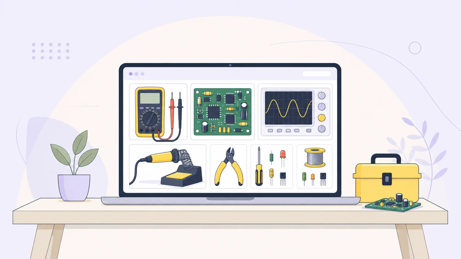
Electronics tools help you build a circuit, check what it is doing, and work out what to try next. A small set of physical tools is enough to start experimenting with low-voltage circuits. Online calculators can help with the arithmetic, but they do not measure a real circuit or replace checking component datasheets.
A practical starter kit
A solderless breadboard and jumper wires let you assemble and change simple circuits without soldering. Breadboards commonly connect groups of holes internally, with a center gap separating the two sides. Power rails may be split, and layouts vary, so check the board’s diagram or test its connections before relying on them. Adafruit’s breadboard guide shows common layouts.
A digital multimeter (DMM) measures quantities such as voltage, current, and resistance, depending on the model. It can help check whether a circuit has the voltage you expect, whether a connection is open, and how much current it draws.
A current-limited bench supply is useful for adjustable low-voltage experiments. A suitable battery or other low-voltage source can also work for simple circuits. A bench supply’s current limit caps how much current it will provide; it does not force the selected current through the circuit. The load draws current according to the circuit and applied voltage. Keysight explains constant-current operation.
Keep a small assortment of common parts, such as resistors, LEDs, capacitors, diodes, and small transistors. Check each part’s value and polarity where applicable: LEDs, diodes, and many capacitors are polarized. Breadboards are for temporary connections; a solderable perfboard can help make a circuit more permanent, but it may not share the breadboard’s connected rows. Adafruit’s comparison of breadboards and perfboards explains the difference.
Getting useful readings with a multimeter
Check the meter’s manual, ratings, input jacks, and selector before using it. Functions and ratings vary by model. These habits help prevent misleading readings and damaged equipment:
For voltage, place the meter across the component or points you want to compare. Use a setting and input suitable for the circuit.
For current, first turn off or disconnect the supply. Open the circuit and insert the meter in series, using the correct current jack and range. After checking the connections, restore power to take the reading.
For resistance, turn off power and discharge capacitors first. Another path through the circuit can affect the result, so an in-circuit reading may not equal the component’s value. Fluke’s resistance-measurement guide covers these limitations.
For continuity, test only an unpowered circuit with capacitors discharged. A beep can help find a connected path, but does not tell you whether that path has the right resistance for your design.
A common meter mistake is leaving the red lead in a current jack, then trying to measure voltage across a source. In current mode, connecting the meter across a voltage source can create a short. Follow the meter’s manual and ratings, and return the lead to the voltage jack when you finish measuring current. Fluke’s meter safety guidance explains why jack choice matters.
A repeatable workflow for a first circuit
A simple workflow helps you find wiring mistakes and understand what your measurements mean:
Describe the goal. For example: “I want an LED to light from a low-voltage supply.” Identify the supply, LED, and resistor, and check the parts’ ratings.
Estimate the component values. For an idealized example, a 5 V supply, 2 V LED drop, and 0.010 A target give: R = (5 V − 2 V) ÷ 0.010 A = 300 Ω. A 330 Ω resistor would give about 9.1 mA under those assumptions. Actual LED and supply values vary, so check the datasheet and resistor power rating.
Build with the supply off. Follow the breadboard’s connection layout. Check component polarity, and make sure leads and jumpers are not accidentally sharing a connected row.
Inspect before powering. Compare the wiring with your sketch, including the breadboard rails, which may be split. Set an appropriate low voltage and current limit for the parts, then turn on the supply.
Measure and adjust one thing at a time. If the circuit behaves unexpectedly, switch off before moving wires. Check likely causes, such as a short, reversed component, or incorrect supply setting, and note each change and reading.
For early experiments, stay with low-voltage battery or bench-supply projects. A current limit can reduce the consequences of some wiring errors, but it does not prove the circuit is correct or make every setup safe. Do not use household mains as a beginner test source.
When to add more tools
A soldering iron is useful when you want stronger, more durable connections than a breadboard provides. It takes practice: the iron tip and nearby metal can cause burns. Use the iron’s stand, wear eye protection, provide suitable ventilation, and never solder an energized circuit. See the University of Illinois soldering safety guidance.
An oscilloscope helps when a multimeter’s steady reading cannot show what is happening over time, such as a pulse or ripple. A function generator can provide test signals for circuits that respond to changing inputs. These tools need careful setup: many bench scopes have earth-connected ground references, so connecting a probe ground to the wrong point can short part of a circuit. Check the scope manual and use appropriate differential probing for floating circuits. Tektronix’s oscilloscope primer and Keysight’s probing note discuss grounding and measurement setup.
You do not need to buy every instrument at once. Start with tools for the measurements and projects you have in mind; borrow specialized equipment when a particular project needs it.
Common mistakes to watch for
Assuming every breadboard is wired the same way. Check its layout and test uncertain connections.
Measuring resistance or continuity on a powered circuit. Turn off power and discharge capacitors first.
Measuring current across a source. Turn off or disconnect the supply before opening the circuit and putting the meter in series.
Changing several wires at once. Switch off before rewiring, and change one thing at a time so you can tell what affected the result.
Mixing units or prefixes. Keep units beside each value; a decimal-place error between milliamps and amps can substantially change a calculation. NIST provides a reference for SI prefixes.
Where online calculators fit
Online calculators help with planning and checking arithmetic. They use the information you provide, so they cannot confirm that a circuit is wired correctly or account for every real-world detail. Use their results as estimates, then check the assembled circuit with appropriate physical tools and component datasheets.
For basic circuit calculations, an Ohm’s law calculator solves for voltage, current, resistance, or power when you know two quantities. An LED resistor calculator estimates a current-limiting resistor, and a voltage divider calculator estimates divider output and loaded behavior. If you are identifying a part, the resistor color code calculator can help decode its marked value.
The site’s Electronics Tools are online calculators, not physical bench instruments. Use them to form a starting estimate, build within component ratings, and then measure what the circuit actually does. You can browse the Electronics Tools collection for more calculators.